'PORTUGUESE' DINGHY

'PORTUGUESE' DINGHY
My first build (2007) - designed by Hannu Vartiaala (Hannu's Boatyard)

Tuesday 6 March 2012

More Kayak Progress


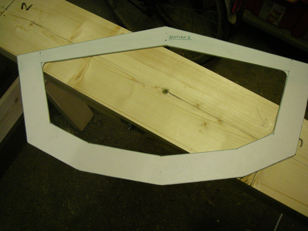
Next step was to use some card to create templates for the bow and stern plates:


This is a bit of a black art. Yost gives some guide lengths for the gunwales, chines and keel but says that you have to judge where they are happiest coming together then set the rake of bow and stern by eye according to what looks best to you.

This took several attempts by trial and error, until I had a couple of templates that I felt were OK:


These were use to mark out the oak planking bow and stern plates, which I then rough fitted in place and shaped up - again by trial and error:

Bow:


Stern:


More frame work to follow ....
23rd FEBRUARY 2011

A bit more on the ups (and downs) in the life of a backyard kayak builder ...

The next task is to measure up and cut the deck ridges to size. There is one running from the Masik to the bow:


and 2 aft of the cockpit connecting frames 4 and 5, which will support the flat rear deck:


all of them are notched where they fit over the frames so that they will lie flush:


The frame itself is temporarily screwed together (using thin 50mm drywall screws through predrilled holes in the gunwales and chines at every junction with the frames):


and the finished result gives me some idea of what I should end up with:


Now for the gluing up the gunwales and chine 1:


with copious use of F clamps, G clamps, spring clamps, quick clamps and Spanish windlasses. I've thickened the epoxy with colloidal silica to make a good glue mix (hollow laugh !).

I left everything for 24 hours, then removed the screws (so that they didn't set permanently in the epoxy) and left things clamped up - but removed the windlasses. I was away from home for the next 12 hours or so. On checking when I got back, I had one of those Oh S**t ! moments that I'm sure are the fate of all BYBBs at some stage:


The glue had given way at 5 of the joints in the bow and 2 at the stern. I think that this happened because of a couple of things:


- my workshop is cold (we have been having seasonally cool weather for the last week or so) and even with an oil-filled heater going full belt, it barely gets up to 12C. This slows things right down and I was probably too fast in removing the screws & windlasses - though everything held when I removed them.

- There may have been some epoxy starvation in the joints as it soaked away into the end grain of the plywood frames:


After taking emergency remedial action to stabilize the whole framework, I then got everything back in order and prepared for re-glueing. I'm also going to glue in the keel so have taped up the support brackets (where the keel goes through under frames 1 & 5) with packing tape:


and all the blocks and wedges used to support the keel in position:


so that the epoxy doesn't stick (I hope !) to places that I don't want it to.

Glueing up again: 


with screws at all joints and no less than 5 Spanish windlasses holding it all together:


The weather is a bit warmer now and I've managed to get the shop up to 19C. I'm going to walk away now and leave things be for 48 hours (may be a couple of visual checks - but no touching).

Next up, glueing up the bow, stern and chine 2 ....

Sunday 5 February 2012

Dinghy Cruising

I enjoy the challenges and rewards of building small boats, but get at least as much please (if not more) from sailing them.  My family sail a Lune Whammel:


she is the one in the foreground of this shot of members of the Dinghy Cruising Association sailing in company.  She is a 17 foot (5.2m) gaff sloop, a design adapted from the inshore fishing craft of the Lune Estuary in the North West of the UK.  We use her for day sailing and dinghy cruising (camp cruising in the USA ?).  She's a good boat for the job but eventually I want to build a slightly stretched (by 10%) version of John Welsford's 'Pilgrim' design; I think that 'Pilgrim' will be an even better design for the waters off the South West coast of Wales where we live and sail.

For more on the Dinghy Cruising Association:


please have a look at our website (in my Links).  Although we are UK based, we have members worldwide.

Thursday 2 February 2012

New Blog - First Post - Last Year's Kayak Build

I thought I would start with a longish post culled from a diary I kept on another forum about last winter's project.  Here goes:
12 January 2011

Change of Plan - From Pathfinder canoe to Sea Bee kayak.

As a result of sustained customer pressure over the holidays, there has been a change of plan. Instead of a canoe, we're going to build a kayak. It will be based on Tom Yost's Sea Bee skin on frame design. His website at
www.yostwerks.com is well worth a visit. The design now has 3 chines and is suitable for ply skinning, so we will end up with a ply framed, softwood stringered, hardwood keeled, ply skinned vessel. 
Sea Bee 13 Kayak

A few photos (credit to Tom Yost's Yostwerks.com and original posters there). Here are the lines for the Sea Bee Multi-Chine from which I adapted my project:


If I get things right, the frame should come out looking something like this (though this is the earlier, single chine version of Sea Bee):


Tom Yost then covered this frame with vinyl to get a finished kayak like this:


and here's another skin on frame (SOF) Sea Bee built in Florida:


I am going to skin the frame in 4mm ply, not fabric - which the designer says is fine (though he doesn't give any clue as to how !). I've adapted the frame plans once lofted to reduce the chines from 3 to 2 to make planking up easier. I intend to use JW's Houdini and Pilgrim simple planking concept - in miniature !

Next step - building the strongback


20 January 2011
Strongback.

Canoe or kayak builders may be familiar with these - I wasn't, so I followed the comprehensive directions on Tom Yost's website. You have to do a bit of interpretation as the example he uses is for a 17' boat and Sea Bee is only 13'. Anyway, I need a strongback that will support the first and last stations (1 & 5) which are 8'6" apart - so I'm choosing to make it 10' long.

The basis is a beam of three 4x2s bolted together:


Which you clamp together. These are the metric equivalent, which are a bit smaller and only 7' long, so each length is made up of a 7' and a 3' bit - staggered. I got four of these as a discount from Focus because they were all a bit warped. I cut the most warped for the 3' lengths and used the straightest as the central timber. A week in my damp garage with the heater turned up to create a humid atmosphere and weights on the bowed section cured most of this.

I then drilled and bolted them together with nine 130mm M8 coachbolts using M12 square plate washers at each end. Bolts were tightened progressively from the centre one outwards alternating each side in order to let tensions ease out towards the ends of the beam.
The next step is to fix on the top plate. The metric equivalent of a 6x1 plank again comes out a bit smaller. Again in a 7' length with a 3' second piece to make up the 10' needed:


I drilled the plank every 18" or so and attached it to the beam with 2 1/2" deck screws.

Then the acid test. The strongback has turned out 100% level end to end. There is a small amount of twist at either end, but overall the cross levels along the strongback are just about within (my) tolerance. Last step this evening was to mark a centre line and the positions of stations 1 and 5. I need to do this as my workshop is a very small garage and I need to position the strongback and supporting sawhorses very accurately in it if I am to be able to fit in the kayak frame and still move about to the bench, drill, etc.

27 January 2011
Lofting the Frames.

Tom Yost's designs come as a series of offsets for the station frames and the cockpit coaming. For his non-folding kayaks, he recommends lofting directly onto the 12mm ply for the frames. However, as I am going to be building this Sea Bee with a plywood skin rather than skin on frame, I decided to loft out the frames onto some white painted 4mm MDF.


This is the first time that I had ever lofted anything, but the instructions about how to do it on the Yostworks.com website are pretty clear. Essentially it's just the accurate plotting of sets of x/y coordinates and then joining the dots. That technical drawing O Level that I did years ago is finally proving to be of some use !

Seeing the frames full size was really useful. It allowed me to see that chines 2 & 3 were really close together - good for getting around the turn of the bilge in a SOF hull, but it would make one of the ply planks far too narrow. Anyway, I then removed chine 2 from all stations and extrapolated the hull lines out from chines 1 and 3 to create a new 2 chine hull profile as close as possible to the 3 chine original.

I also raised the height of frame 3 (the Masik) at the front of the cockpit, as the central space looked too tight and carried that height forward in reducing proportions for frames 2 and 1.

After experimenting with producing card templates by pushing map pins through the lofting board, I decided that I would cut up the board and use what I had drawn as templates. I rough cut each frame out with a jigsaw, then finished off the outside edges with a Japanese pull saw. As a dry run for cutting out the frames themselves, I then cut out the interiors by first drilling each corner accurately with a 20mm Forstner bit, as suggested by Yost:


I then cut around as accurately as I could with a coping saw. This worked well on the first template, but was prettly slow - so I did the other 4 templates with a fine jigsaw blade using a pretty slow speed setting and the results were nearly as good. After finishing off the edges down to the lines with a small Sureform, a woodfile and finally fine sandpaper, I was pretty happy with the result:


Meanwhile, the materials I ordered have been arriving. Ply (hardwood WBP), timber, 6mm dowel and bronze ringnails from Robbins; epoxy and filler from Fyne Boat Kits (the best online deal I could find); glass fibre tape and cloth from East Coast Fibreglass (ditto). Storage is pretty tight in my very small garage, so the 8x4' sheets of 4mm ply for the skin (which I won't need for a while) are stored in the spare bedroom - thank you Domestic Controller !
3 February 2011
Section Frames and Some Work on the Keel.

With the templates all cut out, I then jiggled them around and found that I could fit them all onto a 1/4 sheet of 12mm ply (WBP):


This is another advantage of the template approach; if I had lofted directly onto the ply (as Tom Yost recommends), I don't think that I could have squeezed them all in. I had aimed off for half a sheet of ply - so I'm now a 1/4 sheet up !

Having tacked the templates down with panel pins, I traced around them:


Then cut out very roughly with a jigsaw - just enough to get more manageable pieces. It was then a long, slow process to cut them out accurately using forstner bits, a fine jigsaw and my Japanese saw. Once cut out, I took the external edges accurately down to the marks with a low angle block plane (see separate forum thread on the Anant plane - it is performing really well). Then finished off all the cut outs for stringers with a file and sandpaper before filing and sanding down the internal cut outs. I'm happy with the results:


Section 3 - the Masik (name comes from Greenland kayaks) has a hefty doubler across the top to allow the paddler's knees to be braced against it in comfort. 
I shaped this out of a piece of 4x2" SPF. I'm still not sure if I will use it - it's quite a bit of extra weight and I think I might be able to achieve the necessary bracing comfort with a piece of closed cell PE foam.

With the frames finished, I have started on all the longitudinals. Robbins were unable to supply them in the 14' lengths that I needed, so there is some jointing to be done. I started with the keel. this is 38x25mm oak. Yost says that butt joints are perfectly acceptable and I will be using them for the chine stringers and gunwales, but I decided (after some useful advice following a request for help in the Backyard Boatbuilders UK forum) to do a proper scarph on the keel:


This is at a 1:8 ratio. Cut out roughly with the trusty jigsaw (end cuts with the Japanese saw) then finished with the low angle block plane and some final paring with a chisel. They fit well - but I haven't got a photo to prove it - yet.


19th FEBRUARY 2011

The keel scarph went together well. I clamped it (well wrapped in poythene sheet to prevent unwanted adhesion to anything else) between two 1m long straight battens - having previously drilled the joint for a couple of 6mm hardwood pegs, which positioned the joint nicely:


The stringers and the gunwales were all lengthened with butt joints, using stainless screws to hold them firm while clamping up:


The positioning of the butt joints between frame 5 and the stern later gave me some problems, so I had to plane four of them down a bit so that they didn't interfere with each other:


With a less parsimonious approach to use of timber, I would have staggered the position of the joints more to avoid this. A lesson for the next project, maybe ?

(Added 2 April) These butt joints later gave me another problem. The strain of bringing chine 2 in to meet the stern caused the glue in the actual joints to give way on both sides. Luckily, the butt straps held. I re-glued, reinforced top and bottom of each joint with fibreglass tape and clamped up using battens.


Meanwhile, I intend to create watertight buoyancy compartments in the bow and stern, so frames 1 and 5 have had 6mm ply plates epoxied over the cutouts:


Time to set these 2 frames up accurately onto the strongback - leveled in every possible plane:


First to go on are the gunwales, held on temporarily with bungees:


after which the other frames are persuaded into place and I start to have something that looks as though it might turn into a kayak.  The chines follow in the same manner (this is chine 1):


and I start to use cable ties as a slightly more robust, but still temporary means of attachment. The most useful tool for all of this? A Spanish Windlass:


Once all the chines were in place (which took much longer than writing that phrase !), I then went around with a builder's level and a mallet adjusting the position of the frames so that they were all level then tightening up all cable ties and marking the final positions of the frames on the gunwales & chines.